

Not everything we want to decorate is round. Picture frames, plaques, boxes, and cutting boards invite a different question: could our imaginary gear follow a rectangular track?
That question led to TRIV—the Trochoidal Rectangular Interpolation Vectorizer. Replacing a circle with a rectangle sounds like a small change. It removes one of the most convenient guarantees in the whole construction.
Straight roads and rounded corners
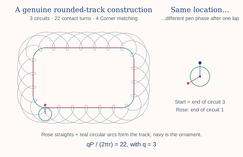
Along a straight side, the rolling circle moves along a line and rotates according to the distance traveled. At a corner, it has to turn. Circular quarter-arcs connect the straight sides into a rounded rectangle, giving the track a common tangent at each join.
The track's direction is continuous, although its curvature changes where a straight meets an arc. We must account for that changing direction as well as the distance rolled. The familiar circular trochoid formulas alone cannot describe this combination of lines and arcs.
Open the full-size diagram
Getting back isn't the same as coming home
A gear can complete one circuit and return to the same place on the track with its pen pointing somewhere else. Stopping there would leave an open seam. A straight connector could close the vector, but it would add a piece that the rolling pen never drew.
For a noncentered pen, both position and rotational phase must repeat. A pen at the gear center is a special case: its visible path repeats after one circuit regardless of the gear's orientation. The distance around the track gives us a way to arrange the general case deliberately.
The perimeter holds the key
Let W and H be the width and height of the virtual track, and c its circular corner radius. Four straight sections and four quarter-circles give a perimeter of:
A rolling circle of radius r has circumference 2πr. For closure after q complete circuits, we choose an integer m so that:
Here m counts turns of the contact phase: accumulated track distance divided by the gear circumference. The tangent itself also makes a complete turn per circuit. With a counterclockwise track, the signed gear rotations in the fixed frame are q + m outside and q − m inside. Those extra whole turns do not prevent closure.
Unlike integer circular tooth counts, integer rectangle dimensions do not automatically satisfy this condition. TRIV selects a compatible frequency and calculates the virtual gear radius:
For a noncentered pen, choosing coprime q and m makes q the first whole circuit count that repeats the complete configuration. If they shared a factor, the motion would repeat sooner.
Persuading the corners to cooperate
Closure and symmetry are different requests. A pattern may close perfectly while looking different at successive corners.
TRIV's Free mode adds no corner-matching constraint. 2 Corner matches opposite corners, while 4 Corner matches all four in the virtual construction. Matching compares the complete corner artwork accumulated across every circuit; corresponding portions need not occur during the same circuit.
These requirements constrain the usable frequencies and, for four-corner matching, the virtual track proportions. Pattern Density selects a rank in that usable-frequency sequence. It is not simply a count of petals or a fixed number of turns per circuit.
The construction establishes closure and corner relationships first. Physical sizing comes next.
Making it fit
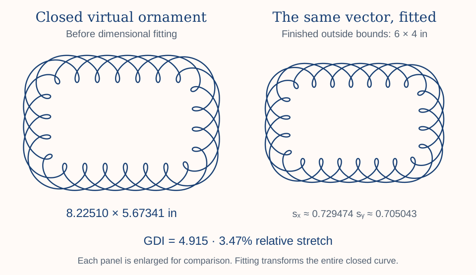
A valid virtual construction may be too wide, too tall, or have different proportions from the intended plaque. TRIV fits the completed Bézier geometry to the requested outside width and height using its actual bounds.
Equal horizontal and vertical scale factors preserve proportions. Different factors stretch the pattern more in one direction. A closed, continuous curve remains closed and continuous under that transformation. Smooth tangent joins remain smooth, too; we are transforming a valid construction rather than pulling mismatched endpoints together.
The trade-off is geometric. Circles can become ellipses, and corners that matched after rotation in the virtual construction may have different proportions after unequal scaling. The specified finished size describes the ornament, not a physical rolling track.
Open the full-size diagram
Measuring the compromise
The Geometric Distortion Index (GDI) describes the difference between the positive scale factors sx and sy:
| GDI | Relative stretch |
|---|---|
| 0 | Unchanged proportions, at any uniform scale. |
| 10 | About 7.18% greater in one direction. |
| 100 | A 2:1 ratio between scale factors. |
| 200 | A 4:1 ratio between scale factors. |
GDI measures proportional change, not interpolation error or machining precision. A larger value is not automatically undesirable; stretching can be part of the design. The number makes that choice visible.
We now have a way to construct a closed border and fit it to practical dimensions. But circular corners have been making the calculation easier than it might appear. What happens when those corners become elliptical—or the entire track becomes an oval?